참고문헌
[1] Encyclopedia of Nanotechnolgy
[2] Nanofabrication Using Electron Beam Lithography: Novel Resist and Applications, Arwa Abbas
[3] UC Berkeley Marvell Nanofabrication Laboratory
[4] Process Optimization on Raith-150 TWO E-Beam Lithography Tool for sub-100nm CMOS device fabrication
0. Definition

EBL은 패터닝을 하는데 있어 기존의 포토리소그래피 처럼 광자를 사용하는 것이 아니라, 전자를 사용하는 기법이다. EBL은 포토리소그래피와 여러면에서 유사점을 갖고 있으며, 아래와 같은 공정 과정을 거친다.
- Spin Coating
- E-beam Exposure
- Development Steps
EBL의 장점에는 sub-10nm 의 feature size까지도 exposure가 가능하다는것, 마스크가 필요 없으며 CAD 프로그램 등을 이용하여 패턴 모양을 쉽게 바꿀 수 있다는 점 등 다양한 장점이 존재한다.
1. Select the substrate that we put a pattern onto.
In the electronics industry for example, we would start with the semiconductor wafer, such as silicon. The wafer is then coated with the thin polymer layer using a process knonwn as spin coating.
Using the same technology as spin coating for photolithography, but using the special resist, that is sensitive to electrons. The EBL resist.
Soon we expose the polymer to the beam of electron, the polymer undergoes the chemical change. This EBL resist is also very thin. Since a thin resist is needed to create very small feature sizes.
The resists thickness may range from tens of nanometers to a few hundred nanometers depending upon the desired process and feature size.
전자와 충돌시 반응하여 없어지는 PR을 사용하여 노광과정에서 전자를 사용한다.After electron beam exposure the chemistry of positive resists results in polymer chain scission, reducing the polymer chain length; therefore, the exposed area in resist is more easily dissolved in developer than the unexposed resist.
After electron beam exposure the chemistry of negative resists of the exposed areas become cross-linked with the polymer chains; therefore, it is more difficult to dissolve the cross-linked polymer in developer.
(+) Mask 사용 안하는 direc patterning,
(+) 렌즈 필요없이 10nm의 resolution까지 가능
(-) Throughput이 매우 작음
(-) 진공환경이 필요하여 단가가 매우 비쌈
이러한 단점들로 인해 산업현장 보다는 R&D에 주로 쓰이며, Photomask 제작에도 사용된다.
(-) 전자의 scattering이후, 2차, 3차 scattering이 발생하여 PR의 아래쪽이 더 넓어진다. (Undercut profile)

EBL is quite a complex instrument.
But its basic component is as follows
There is an electron source, which is a small sharpened tip, that emits a stream of electrons, when a high voltage bias is applied. We call this emitted electrons the electron beam
Next, is electromagnetic lens system. Here is show of cross sectional view. The lens system focuses the beam of electrons.
The major difference in focusing electrons and a major advantage of EBL compared to photolithography is that an electron beam can be focused to extremly small spot size less than 5 nanometers in diameter.
Now, below the lens system, is a set of beam deflectors. Beam deflectors can electronically deflect the focused beam of electrons at extremly high speeds. This controls the position of electron beam allowing the beam to be steered to different regions of the substrates.
Typical beam deflectors, can move the beam to one position to another, in the matter of nanoseconds. So it's very fast.
The electron source emits electrons, the lens system focuses the beam, the deflector steers the beam across the subsrate.
The beam deflectors direct the beam across the substrate based on the pattern you have drawn using the CAD program and that you loaded in the EBL system.
A pattern can be simple or complex as you wish . You may only have a few shapes to pattern, or you may have a millions shapes to pattern. All of this is computer controlled and very fast.
ㅡㅡ 5:29
리소그래피는 나노공정에 있어 필수적인 요소이다. 지난 10년간, 전자 디바이스의 CD는 급격하게 감소하였으며 회로 복잡도는 상승하였다. 결과적으로, 전자 소자 공정은 나노미터 영역까지 도달했다. 이러한 필요 조건들을 충족시키기 위해서
EBL: The process of transferring a pattern onto the surface of a substrate.
- Spin Coating
- Exposure
- Developing
The advantage of e-beam lithography stems from the shorter wavelength of a accelerated electrons compared to the wavelength of UV light used in photolithography.
there are two types of nanofabrication approaches: bottom-up and top down
In bottom-up approaches, 아래와 같은 기술들이 포함되어 있다.
- chemical synthesis of nanoparticles (nanoscale particles, wires, tubes, and other shapes like cones, and cages)
- self-assembly of nanoscale blocks into ordered array of structures
- nano-sphere lithography, template-based methods that exploit nanoporous membranes (notably anodized alumina), self-assembly of block copolymers,2, 3, 4, 5, 6, 7 self-assembly of atoms and molecules, and supramolecular elements.
Top down 방식으로는,
the manipulation of structures of bulk materials by eliminating or adding nanoscale patterns. The lateral size is determined by the lithography process, whereas the vertical one by thin film deposition and etching techniques. Nano-lithography techniques include ion beam lithography, electron beam lithography (EBL), nanoimprint, and scanning probe lithography.
There are two types of lithography techniques. The first type duplicates the pattern of the mask, including optical lithography or charged particle projection lithography, x-ray lithography5 (XRL), extreme ultra-violet lithography5 (EUVL) and nanoimprint lithography 6 (NIL). The second type is direct patterning that generates the pattern, including electron beam lithography (EBL),9,10 ion beam lithography (IBL), scanning probes 5 (SPL), and electron-beam-induced deposition (EBID).
Lithography와 다른 패터닝 기술의 발전을 촉진시키는 두가지 요인은 두가지이다.
- 더 높은 해상도(resolution) ( = for smaller feature size)
- 가격
Optical lithography 영역에서, 해상도는 우리가 사용하는 광원의 파장과 numerical aperture (NA)라는 파라미터를 이용하여 조절한다. 이때 파장을 짧게 하여 해상도를 증가시키는 데는 한계가 있으므로, 반대 급부로 NA를 증가시키기 위해 lens immersion, phase shifting 등의 다양한 기술들이 사용된다. 하지만 이 기술들은 가격, 그리고 노광 횟수들을 지속적으로 증가시키므로 복잡도를 상승시킨다. 그렇기에, 새로운 기술들은 빛의 diffraction limit을 깨기 위해 적응해야 한다.
1. Principles of Electron Beam Lithography
nm 스케일 패터닝을 하는데 있어 EBL의 강점은 전자의 짧은 파장으로 부터 온다. 움직이는 전자의 파장은 de Broglie 방정식에 따라 주어진다.

전자는 전기적 포텐셜 U에 의해 다음의 속도까지 가속된다.

이 경우, 전자의 파장은 아래와 같이 나타낼 수 있다.

전자 현미경의 경우, 가속 포텐셜은 일반적으로 수천 볼트 정도이며, 전자가 빛의 속도보다 매우 작은 속도로 움직이게끔 한다. 10 kV의 가속 포텐셜에서 작동하는 SEM은 빛의 속도에 약 20% 정도이며(파장은 12.3 pm 정도), 200 kV로 작동하는 일반적 REM은 빛의 속도에 약 70% 까지 전자의 속도를 끌어 올린다(이때 파장은 2.5 pm 정도). 그러므로 우리는 상대론적 효과를 고려해야 하며, 전자의 파장은 아래와 같이 수정되어야 한다.


As an example, the Raith 150TWO for the nanofabrication work presented in this thesis features a tungsten filament Schottky emission gun, a maximum stable accelerating potential of 30 kV, and typical working distance of 10 mm (smaller working distance gives smaller beam spot size, but with higher risk of sample hitting the electron column).
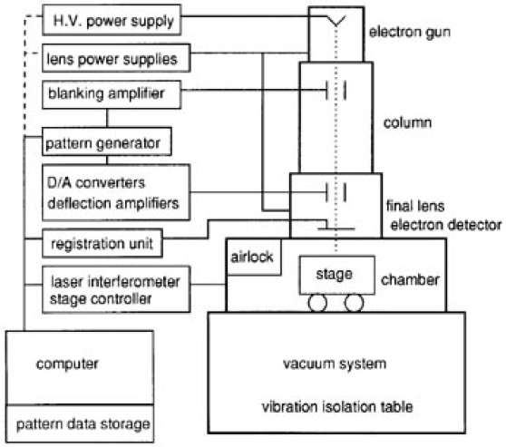
위 그림은 EBL의 개형을 나타낸 것으로, 다음의 것들을 포함하고 있다.
- Electron gun = 전자 빔 소스
- 직렬 형태의 condenser, objective lense: beam의 직경과, 샘플 위 beam의 포커싱을 조절
- 전자, 또는 정전기적 deflector: focused beam을 specimen의 표면에 회절시킴
- Beam blanker: aperture와 deflector의 조합으로, beam을 끄는데 사용
- 여러 Aperture들: beam의 물리적 성질에 영향
- Laser interferometer stage: loading, unloading, 챔버 내의 샘플 이동
- Column의 High vac 상태( 2*10^-9 mbar)를 유지하기 위한 진공 시스템
Column으로부터 발생한 FEB는 샘플의 원자핵, 전자의 쿨롱력과 인터렉션 할수 있다. 이 인터렉션은 다양한 이벤트를 야기한다: inelastic events, and elastic events. (아래 그림 참조)

전자가 specimen을 타격할 때, 전자는 specimen 속 원자의 전자가 만들어내는 전기장과 상호작용 한다. Hence, there is a potential expulsion of an electron from specimen atom due to transfer of energy to that atom. These electron are known as secondary electrons and have energy, typically, less than 50eV. This is referred to as inelastic event.
Elastic events는 specimen을 타격하는 전자가 specimen 원자의 원자핵이 만들어내는 전기장과 상호작용할 때 나타나며, 전자의 운동에너지를 크게 변화시키지 않고($< 1 eV$) 운동 방향을 바꿔버린다. 이 elastically 스캐터링된 전자는 방향을 바꿔 specimen으로부터 다시 specimen을부터 튀어나오며 back scattered electron (BSE)라 불린다. BSE는 에너지를 50 eV부터 클 경우 입사될 때의 에너지를 그대로 가지고 나올 때도 있다. 하지만, 일반적으로 대부분의 BSE는 입사 할때의 에너지보다 절반 이하의 에너지를 가진채 튀어나온다.

이 처럼 specimen으로 부터 튀어나오는 secondary 전자들은 디텍터에 의해 신호로 잡히게 되며, 처리 과정을 거쳐 모니터 디스플레이에 이미지 또는 스펙트럼 형태로 관측된다.
1.1. Column Controller - Heart of Lithography
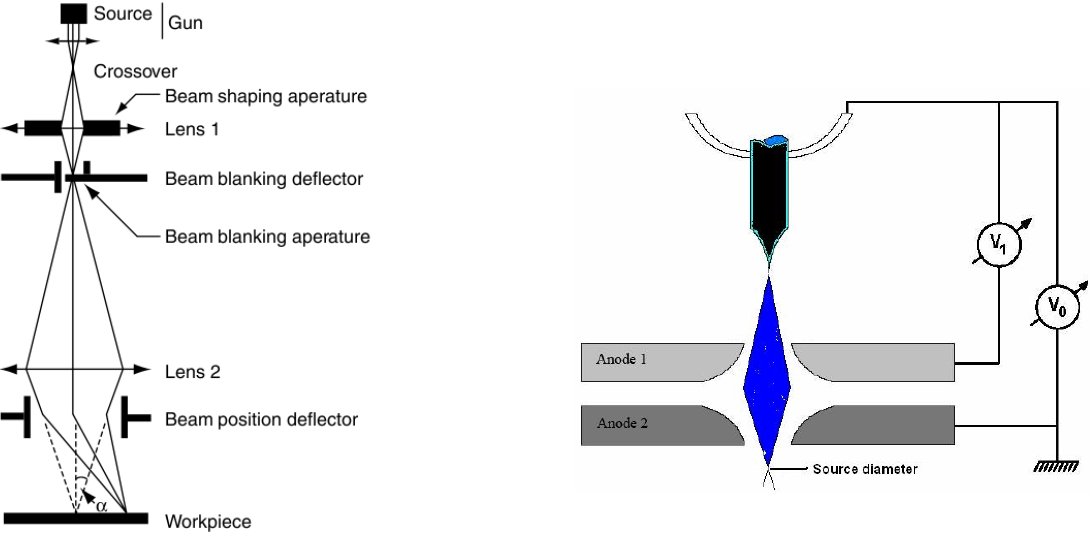
Electron column은 EBL의 심장과도 같다. Round-beam EL instrument의 단순화 된 ray diagram은 아래와 같다.

Round-beam 뿐만 아니라 다양한 Shaped-Beam instruments도 가능하다.(fixed square-spot instruments and shaped rectangular-spot instruments)
Round-beam machine에 의해 만들어지는 Spot 내에서의 전류 밀도는 균일하지 않기에, bell-shaped distribution을 만들어낸다. 더욱이 Pfieffer와 Loeffler는 pointed out that electron optical systems that produced square, uniformly illuminated spots, could be built.
1.1.1. Filament and Electron Emission
Column은 전자를 방출하는 필라멘트를 포함한다. Raith 150 TWO 시스템은 Schottky field emitter를 사용하며, 이는 ZrO/W으로 만들어지는 thermal field emission (TFE) cathode이다. 전자는 extractor voltage로서 가해지는 전기장에 의해 heated W tip에서 부터 방출된다. The emitter consists of a sharply pointed single crystal tungsten lament, oriented along <100> axis. The shank of the filament tip is covered by a zirconium oxide (ZrO) reservoir. The single crystal tungsten filament is mounted onto a polycrystalline tungsten heating lament. Tip radius is 0.5 um (+/- 0.1 um)
1.1.2. Beam Spot Size Variation
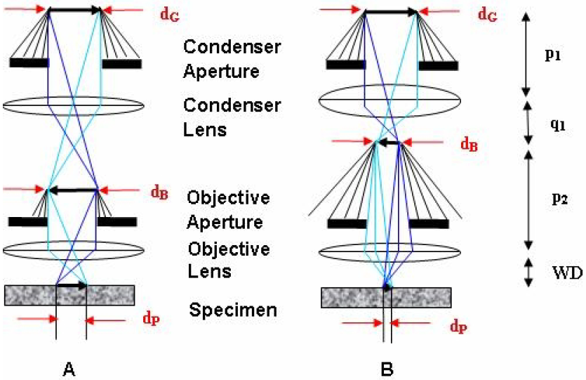
아래 그림은 shows a simplified column with one condenser lens, an objective lens, and an aperture for each lens.

위 그림에서 A와 B는 fun을 빠져나가나는 전자 빔의 source 직경이다. $d_G$는 필라멘트 팁의 직경, $d_P$는 probe의 diameter이다. source diameter의 beam에 대한 de-magnification의 정도 $d_B$는 아래와 같이 나타난다.

마찬가지로, electron probe($d_P$)에 대한 $d_B$에서의 de-magnification의 정도는 아래와 같다.

그러므로, electron probea t the specimen의 직경은 아래와 같이 주어진다.

The magnitude of excitation current of condenser lens in B is high as compared to that of A which causes more of the beam to be stopped by the objective aperture and thus a reduction in probe current occurs. Thus, the probe diameter or the spot size can be varied by altering current to a condenser lens.
1.1.3. Astigmatism Correction
The electromagnetic lenses used in a SEM are not always perfectly symmet-rical. A converged beam would appear circular on the specimen provided the fields produced by the lenses were perfectly symmetrical. If not, then this results in streaking of image on both sides of focus. Even if streaking is not evident, astigmatism still needs to be fine-tuned to obtain high quality images.Objective lens astigmatism can be compensated by applying current dif- ferentially to a ring of stigmator coils around the objective lens. (refer Fig. 1.9)

1.2. Raith 150-TWO System Specifications
Terminology For lower % HSQ, onset Dose becomes higher
Typical spin coat thickness
XR-1541-004 Resist: 55-115nm
EBL Resists
Photoresist는 특정 파장 영역의 가시광선(특정 에너지의 광자)에 민감한 polymer chain이며, 해당 파장의 빛이 조사 될 경우 polymer의 물리적 구조가 변화된다. E-beam resist는 광자가 아닌 전자에 민감한 polymer이다. 이 ER에는 크게 두 가지 종류가 있다. 바로 positive와 negative이다.
Positive ER의 경우, 전자가 조사될 때 long polymer chain이 파괴되며, polymer는 현상액에 기존보다 더 용해되기 쉬워진다. 대표적인 positive ER에는 PMMA, ZEP-520.28,29,30 시리즈 등이 있으며, PMMA가 널리 쓰이는 이유로는 쉬운 작업성, 낮은 가격, 그리고 높은 해상도를 제공하기 때문이다. ZEP-520의 경우 PMMA와 비슷한 효과를 보이지만 더 높은 sensitivity와 etch resistance를 제공한다.
Negative ER은 전자가 조사됨에 따라 shorter polymer chain을 더 강력하게 결합시키며, 현상액에 대한 용해성이 기존보다 떨어지게 된다. 대표적으로 SU-8, ma-N 2401, HSQ 등이 negative ER에 쓰인다.

Resist Sensitivity
Resist sensitivity는 조사된 전자에 대해 polymer가 반응하는데 필요한 에너지의 양으로 정의할 수 있으며, 일반적으로 아래와 같은 조건에 따라 sensitivity 정도가 달라진다.
- Resist thickness
- Resist composition
- Development conditions
- Accelerating voltage of electron beam
일반적으로 EBL 시스템에서 조절할 수 있는 제 1의 팩터는 Accelerating voltage로, 이 값을 키움에 따라 resolution과 undercut(Positive의 경우)이 감소하지만, 반대로 더 많은 backscattering에 의한 강력한 proximity effect, 그리고 높은 resist sensitivty(더 높은 도즈를 필요로 함)를 유발한다.
The highest resolution of ~5 nm features has been achieved by EBL using inorganic resists.13 The widespread use of these resists is usually hindered due to their low sensitivity. HSQ is one of the most commercially and scientifically successful EBL resist, but it displays relatively low sensitivity. Therefore, inorganic resists have been recently prepared, which exhibit higher sensitivity while maintaining high resolution.
1.2.4 Electron Scattering and Proximity Effect
가속된 전자가 ER(더 나아가 기판)을 scattering을 함에 따라 전자가 조사된 영역이 실제 beam size보다 더 커지는 현상을 야기한다. 높은 에너지를 가지는 전자가 ER을 inelastic scattering할 때 10~50 eV정도의 에너지를 가지는 secondary electron이 형성될 수 있다. Scattered electrons은 두 그룹으로 나누어진다.
우선 첫번째로는 각도가 90도 미만으로 scattered 되는 그룹과, 90도 이상으로 scattered되는 그룹이다. 두 scattered electrons의 그룹은 각각이 forward electrons, 그리고 backward electrons로 나누어진다. 여기서, 더 큰 원자핵과 더 큰defelction angle scattering을 가지는 경우가 elastic이며, 이는 전자와 원자 핵 사이의 질량 mismatch 때문이다.
Forward scattering은 beam의 경로를 넓히는데, 일반적으로 accelerating voltage가 낮을 수록 deflection의 정도가 커져 더 큰 proximity effect 결과를 나타낸다. 일반적으로 forward scattering에 의한 proximity range는 나노미터 사이즈이다. Backscatterd electron의 경우에는 resist를 re-expose하는 결과를 내놓는데, 이러한 backscatter의 효과는 수십 마이크로미터까지 그 영향을 끼친다.

Backscattered electron은 의도했던 beam exposrue 영역 이외에 있는 ER에도 추가적인 exposure를 시키는 결과를 내며, 이를 EBL proximity effect라 한다.
이 scattered electrons의 효과는 double-Gaussian model을 통해 기술된다.

위 식에서 $r$은 beam position으로 부터의 radial distance, $\beta_f$는 forward-scattered electron range, $\beta_b$는 backward-scattered electron range 이다.
ßf is the forward scattered electron range (finite incident beam diameters are also modeled in ßf);
is the ratio of integrated exposure from backscattered electrons relative to forward scattered electrons; and ßb is the backscattered electron range.
위 식을 종합하자면, double Gaussian model의 parameter는 incident beam energy, spot size, 그리고 ER과 기판 물질이 포함된다. 하지만, 위의 Fig1.5.와 같이 조사된 영역에 대한 기술은 double-Gaussian model에 추가적으로 exponential term을 더함으로써 더 명확하게 된다. (이는 pattern size가 0.1$\mu$m의 오더일 때 존재한다.)

위의 Fig.1-7은 실리콘에 대해 25 keV일때의 double Gaussian model을 보여준다. The actual exposure distribution is created by convoluting the point exposure response with the desired exposure pattern, and the areas not directly exposed by the incident beam are instead exposed by scattered electrons as a result of the influence of the proximity effect.
To minimize the effect of proximity exposure, one way is to carry out the exposure on a resist coated on a membrane that is transparent to electrons (thus no backscattering). The proximity effect can also be compensated to a certain degree by Mont Carlo simulation and according dose adjustment. Certainly, proximity effect is less significant when the pattern is sparse, or when the pattern area is less than the range of backscattered electron.
The film thickness depends on the polystyrene concentration in the solvent and spin coating speed, ranging from 30 nm for 1.2 wt/vol% to 260 nm for 10 wt/vol concentrations. The film was baked at 60oC for roughly half an hour on a hotplate. Though typical polymer film can be baked at temperatures much higher than its glass transition temperature (e.g. PMMA is usually baked at 180oC), the thin polystyrene film having low molecular weight was not stable at baking temperatures above 80oC, and thus we choose this very low baking temperature.
Electron beam lithography was performed at 20 keV and 5 keV using a LEO 1530 field emission SEM that is equipped with Nabity nanometer pattern generation system (NPGS) and a Raith 150TWO e-beam lithography system. The pattern contains arrays of large squares with a side length of 5 μm with exponentially varying doses that were used to obtain the contrast curve, and arrays of dense periodic lines that were used to determine the achievable resolution. The lines were exposed by single-pass exposure with a step size of 12 nm. After the exposure, the samples were developed thermally on a hotplate at 200oC to 350oC for 0.5-5.5 hours. Some samples were first developed using regular solvent developers (xylene for 30-72 sec, followed by rinsing with 2-propanol), then thermally developed in order to find out the development rate (nm/sec). After development, the contrast curves were obtained by AFM measurement, and high resolution images of the exposed pattern were acquired using LEO 1530 SEM.
4.2 Dry Liftoff
In dry liftoff, the patterned film coated with the metal is peeled off the substrate, rather than dissolved by a solvent. Obviously the adhesion of the resist to the substrate should not be too strong, as otherwise the film will be broken during the peel off process. Some materials such as polycarbonate have weak adhesion to the silicon substrate, thus it can be peeled off easily by using scotch tape. Other materials such as PMMA have strong adhesion to silicon wafer, thus the substrate surface must be modified with a surfactant which has a low surface energy (e.g. a self-assembled monolayer (SAM) of perfluorooctyltrichlorosilane (FOTS)) in order to reduce its surface energy such that the PMMA can be peeled off. However, the surface energy cannot be too low, as otherwise the resist solution will form droplets on the substrate surface, and thus a uniform resist film cannot be coated onto the substrate by spin-coating. In addition to surface energy and adhesion, another important factor is the resist cross-sectional profile.
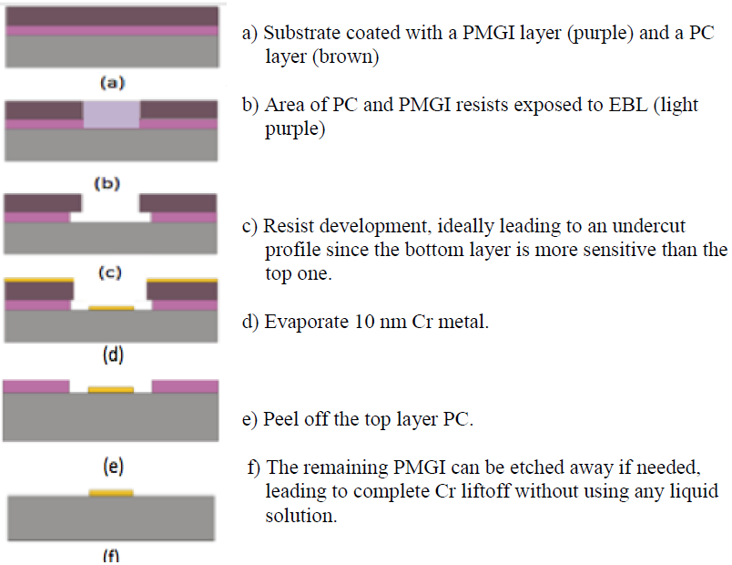
An undercut profile is ideal for liftoff process. As seen in Figure 4.2, with such a profile, the metal on top of resist is not connected to the metal on the substrate. Otherwise, with a tapered (V-shaped) profile, the metal film on top of resist will be connected to the metal on the substrate through the metal coated on the sidewall (now that the sidewall is tapered). Therefore, it would be very difficult to obtain a clean lift off pattern.
PMGI (polymethylglutarimide, SFG 2 S from MicroChem Corp.) is a very popular liftoff layer, so it is chosen for our purpose. Initial test showed that, as expected, PMGI didn’t detach from the silicon wafer since it adheres strongly to silicon; instead PC detached from the PMGI layer. This is acceptable for dry liftoff since the metal on top of the resist layer is removed when PC is peeled off. We expected to achieve an undercut profile because PMGI is a more sensitive resistant than PC (PMGI is exposed during the exposure of PC). We designed the process steps as shown in Figure 4-4.

'반도체 공정& 소자 > Etching' 카테고리의 다른 글
| Undercut profile of ER in nanofabrication (0) | 2023.05.16 |
|---|---|
| Lithography - Etching Techniques (0) | 2021.07.19 |


댓글